CAE Performance Products |
|
     
|
| Stockists F.A.Q. Gallery Shipping Video Policy | |||||
|
|
If you have any problems fitting our products please browse Frequently Asked Questions. If you can't find the answer here don't hesitate to call CAE on 03 5472 1442. If you don't have a copy of the instructions you can download it on the Documents page. Frequently Asked Questions. |
||||||||
| Question | Answer | |||||||
|
E.F.I Loom E.C.U or P.C.M Frequently Asked Questions |
||||||||
| What do I do if the OBD (On Board Diagnostic) Scanner displays a P1336 (Crankshaft position (CKP) system variation not learned) code. |
The diagnostic code (P1336)
is to tell you that the OBD has disabled the Misfire monitor, due to
the crankshaft variation not being learned. This can happen if the
PCM (computer) has been recently re-flashed for engine conversion, or
where the engine & PCM were not from the same vehicle. This re-learn procedure can be done by any GM Holden dealer via their Tech II programmer. For engine conversions the dealer may require donor vehicle original V.I.N. (Vehicle Identification Number) for dealer to gain access. This only applies to Holden Vehicles Manufactured in Australia. This diagnostic code will disable the misfire monitor, and not warn the driver that the engine has entered a dangerous misfire event, which can cause catalyst damage & higher than usual emission readings. This code should not effect the overall vehicle operation, and should not disable engine in any way. |
|||||||
| System Scan: If encountering problems such as engine management light staying on, automatic transmission not shifting properly, speedo not working etc. |
It is advisable to scan system
with Tech 2 or a good quality scan tool. Record all faults and advise us either
by email, fax or phone. System can be manually scanned as per workshop manual
procedure. |
|||||||
| Where do I mount ECU? (Computer) |
Most ECU's all mount either on the LH
kick panel or above the Glove box. GEN IV LS-3 engine ECU mount on drivers side
front inner guard behind headlight. |
|||||||
| Cable-x not working? |
1) Is it wired correctly Red = Ignition,
Black = earth, White = signal input. 2) If connecting direct from PCM (Computer) speedo signal you need to use a 4.7k ohm pull up resistor. 3) Read instructions supplied in box and set the trim switches accordingly. |
|||||||
| Auto Trans goes in to 3rd only. |
Vehicle in limp home mode. Scan vehicle
for fault codes. |
|||||||
| Fuel pump not working. |
Check all plugs for pins that may have become dislodged. |
|||||||
| Cranking issues. |
Place a test light on solenoid wire
and check to see if there is power. If vehicle was previously an Auto check
park neutral switch has been bridged. |
|||||||
| Engine cranks and fires on start but cuts out when key is released. |
Ignition by-pass wired wrong. Follow
instructions provided. |
|||||||
| Engine starts and runs but will not rev over 2000rpm and cuts out. |
If on Holden 12volt with ballast
resistor. The Ballast has not been by-passed. Follow instructions. |
|||||||
| Vehicle fires but cuts out within 2 seconds | Has VAT's
(Vehicle Anti Theft) been programmed out of ECU (Computer).
CAE Performance Products provide this service. |
|||||||
| Speedo and Tacho not working. | 1) Check all
wiring speed sensor and tacho signal 2) Depending on Speedo brand it may need 4.7k ohm pull-up resistor. |
|||||||
| Pedal not working with TAC module. | Reprogram TAC -
check and see if pedal assembly matches application. |
|||||||
| AC re-gassed but still not switching by switch. | Check for positive
switching at A/C switch. Bridge pressure switch. |
|||||||
| GENIII loom into a VN had no positive feed into ECM (Computer). |
Check for correct wiring down
in kick panel. Positive is Pink wire, which is on with ignition. |
|||||||
| Transmission not shifting gears | Check with
ECU(Computer) scan tool: If low voltage code for trans. is logged. Check 12volt
supply at trans plug (pink/blue wire) |
|||||||
| Where do I fit temp. and oil sender's for my gauges on a LS1 - LS2 - LS3 - LS7? | You will need
Temp-Sender adaptor kits from us and a T-piece for Oil Sender. Then simply
screw into where factory oil sender is fitted at rear of engine. Temp Sender
is to be fitted into Hex key bung at rear of driver's side cylinder head. |
|||||||
| What Senders do we use to get factory oil and temp. gauges to work on a new engine transplant? |
Original Senders from
original engine will be required to be fitted for the Gauges to work
correctly. |
|||||||
| Which sump do I use on my VB to VS LS-1 LS-2 engine conversion? | If using the
LS-3/GEN-4 VE Commodore engine you need to have the sump changed to Pre-VE
to suit all early Commodore conversions. All earlier engines LS-1 and LS-2
use VT-VZ standard sump. |
|||||||
| FUEL TANK MODSIFICATIONS | ||||||||
| How do I fit an in-tank fuel pump in my old tank? |
You will need to remove the old tank and determine where there is room to
fit the pump. Make sure that the pump pick-up will sit on the bottom of the
tank, if not full capacity will not be utilised. If possible retain the original
fuel sender and make sure new assembly does not interfere with it. 
 Early Chev Tank - - - - - - - - - - - - - - - - - - - - - - Holden HK-T-G Tank 
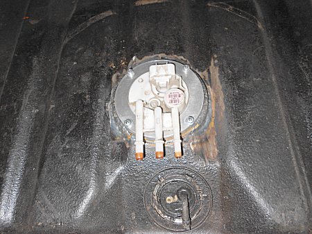 Holden HQ-WB tank requires modification to top and bottom so the EFI pump will fit.
|
|||||||
|
Wiper Arm and Blades F.A.Q. |
||||||||
| 10" Curved Screen Blades. |
These are P/N TE103-10 and match
up to the adjustable Arms P/N TC203. When fitting the spoon arm end into the
Blade Holder, it is very tight to feed into the Blade Holder. To assist
fitment it is advisable to slightly taper the very end of the spoon by
touching the end on a grinding wheel on both sides and the bottom edge of
the spoon, this should help you to slide the spoon into the blade holder
with a fair amount of push required to get it in and located fully home in
its holder. Details in the Arm package shows the lengths to be cut and
locking it into the spring loaded Arm housing.. |
|||||||
| 10" Flat Screen Blade. |
These are P/N TE101-12 Blades
and match up to P/N TC204 Arm which include the small blade attachment hook.
These Blades are designed to be cut at both ends to the height required on
your windscreen. These are best cut with a good pair of 6� Side cutters.
Details of where to cut the Arms are written in the packaging instructions.
To assist in holding the small clip, it is advisable to crimp the clip on to
the arm where the dimple in the arm protrudes through the clip. |
|||||||
| 18" Curved Screen Blades. |
These are P/N 3021180 Blades and
match up to P/N A101 or TC201 Arm. In the Blades packaging, you will find a
small black plastic fitting that clicks on to the blade and is held in place
by the small steel axle pin. The flat Arm, P/N A101/TC201 gets cut to the
correct length and the angled end with the dimple, slides into the plastic
clip all the way until the dimple clicks into the locating hole in the plastic clip. |
|||||||
| Working out the correct length of the Arm and Blade. |
The easiest way is to do this, is to
hold the Blade in the vertical position on the windscreen where you want it to
sweep. Tape this to the Arm assemble in this position so you can visibly
see where on the underside of the Arm you need to make the cut. Make sure there
is enough length to be able to secure it with the small grub screw provided on the arm
assembly. Once the cut is made remove the tape and slide the flat section of
arm into its holder and fasten with the grub screw provided. |
|||||||
|
Adjusting the Wiper Arm Sweep Angle. |
||||||||
| Can I change the Angle of Sweep. |
CAE Performance Products Wipers are supplied
with either 100 or 120 degree of sweep angles. We do have a range of gearwheels
in 10 degree increments available that we can exchange for you. When measuring
the angle it is necessary to quote an angle 10 degree less than you actually
require as this allows for the 5 degree �flop� at the end of each directional
travel. In 90 % of applications the 100 degree and the 120 degree gearwheels
give the correct sweep. |
|||||||
|
Adjusting the Wiper Arm Park Position. |
||||||||
| A - Park Position of the Wiper Blades. |
If the Blades are parking too far
up the screen and wiping too far off the screen, then it is a simple matter of
stoping the wiper motor in the par position. Then remove the arms off the splined
Knurls (Drive post) and moving them around the knurl to the correct position and
pressing them back into place on the drive post knurls. |
|||||||
| B - On Cable Drive Wipers (Horizontal Parking) |
When the Wiper Blades are working
correctly but the park with the blades in the vertical stop position. The
gearwheel inside the wiper motor needs to be removed and the steel Pin
Drive Plate must be rotated 180 degrees on the nylon gear. CAE can do this
for you if necessary. |
|||||||
| C - On Cable Drive Wipers (Clap-hands Type Parking i.e. both Blades pointing towards each other) |
when the Wiper blades are parking
with one Blade vertically stopped and the other blade has stopped in the
correct horizontal position, then one of the wheel boxes and its drive
cable requires rotating 180 degrees compared to its mate. The wheel boxes
must have the spiral drive cable and tubing running underneath the wheel
box on one side wheelbox and over the top of the wheelbox on the other side.
This means there will be a slight s shape in the Middle connecting tube so
the cable drive can run under and the over on the wheel boxes. |
|||||||
| D - On Mechanical Arm Drive Wipers |
When the Wiper blades are not
parking correctly, undo the drive nut on the Wiper Motor shaft that holds
the Wiper Crank Z bracket and gently tap the crank loose from its spline,
rotate it by hand until the wiper blades have dropped down to where you
want them to park. Press the crank back on to its shaft spline and tighten
the shaft nut. Re test and adjust the blades on the outside posts and allow
for a wet screen and an �end flop� factor. |
|||||||
|
Wiper Motor Wiring. |
||||||||
| Wiper Wiring. |
CAE supplied Rotary Wiper Switch
is designed to suit the internal earthing circuit for the self park position
on all Wiper motors. Our Wiper motors can also be connected to stalk type
positive switching switches with modifications that must be carried out by
us to avoid losing the 12 months Warranty. All CAE Wiper Kits are supplied
with the interconnecting Loom and Fuse between Wiper Motor and Rotary type Switch. |
|||||||
|
All CAE Wipers are fitted with a standard 6 Pin Wiring Plug as per diagram below: -- |
||||||||

|
||||||||
|
Wiper Mounting Bracket |
||||||||
| Mount bracket does not suit my application. |
The Universal Mounting bracket for
Cable Drive Wiper Kits, has been
developed to suit most home built cars or restorations. It is impossible
for us to develop a mounting bracket that would suit every make and model
vehicle, but a universal mount is supplied in the kit to give you a starting
point for mounting the Wiper Motor. It can be cut, redrilled or lengthened
to suit your application. Some applications may require another strip to
lengthen the clamp mounting and some times a box section of steel is
required for the mounting bracket to sit on. Drill it; bend it to suit your
own application. |
|||||||
|
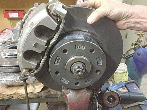
Disc Brake Conversion to suit Can have either HQ-WB or VT-VZ Stud Pattern |
||||||||
|
Fitting a Brake Disc and Caliper Conversion Kit Click for larger image |
|
|||||||
|
57Chev Pivot Posts |
||||||||
| Are there longer Posts available? |
We have had requests for longer Wheel boxes/Posts which we are unable to obtain.
The Aluminium posts (Wheel boxes) are the same length as the original post but
on some Chev cowls and the inner panels, have varied in production.
It may be necessary to panel beat the inner panel slightly so a flatter surface
is obtained. This will allow the wheel boxes too seat correctly and give the correct
length protruding on the outside sufficiently to get the original Chrome nut
to fit and tighten on to the Windscreen retaining bezel. Be careful when
tightening the Chrome nut as it is easy to strip the aluminium threaded wheel box post.
|
|||||||
|
Spiral Drive Cables |
||||||||
| How long can the spiral drive cable be, in the Cable drive kits? |
The manufacture will not accept warranty on cables longer than 2.2 mtrs.
This is due to the limit of effort by the motor to push the spiral
cable through the 5/16" bundy tubing. Cables 900mm, 1200mm, and 2.2mtrs
are available from CAE Performance Products. Any excess cable length can be cut
off using a 4" Grinder with a narrow cut off disk. The Bundy Tubing end
piece should be long enough to completely enclose the spiral drive cable
when it is operating back and forth. |
|||||||
|
Hi-Torque Starter F.A.Q. |
||||||||
| How do I set-up a remote starter solenoid for FE engine in a Ford, Mustang to Thunderbird's etc. and most early English vehicles. |
|
|||||||
|
Hi-Torque Starter - How to measure the OUTER MESH |
||||||||
| How to measure the OUTER MESH |
|
|||||||